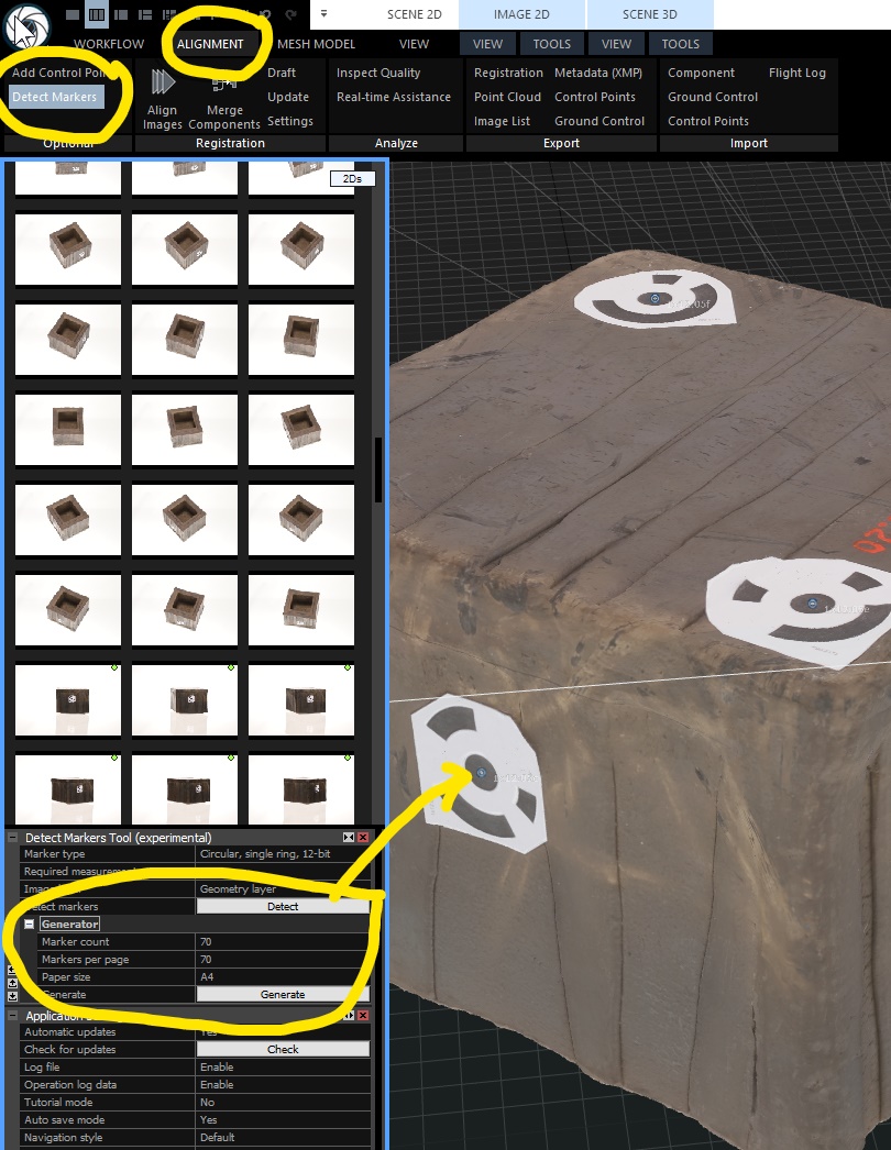
Generate markers by going into ALIGNMENT tab, then DETECT MARKERS and in the menu below se the MARKER COUNT, MARKERS PER PAGE and PAGE SIZE and then hit GENERATE.
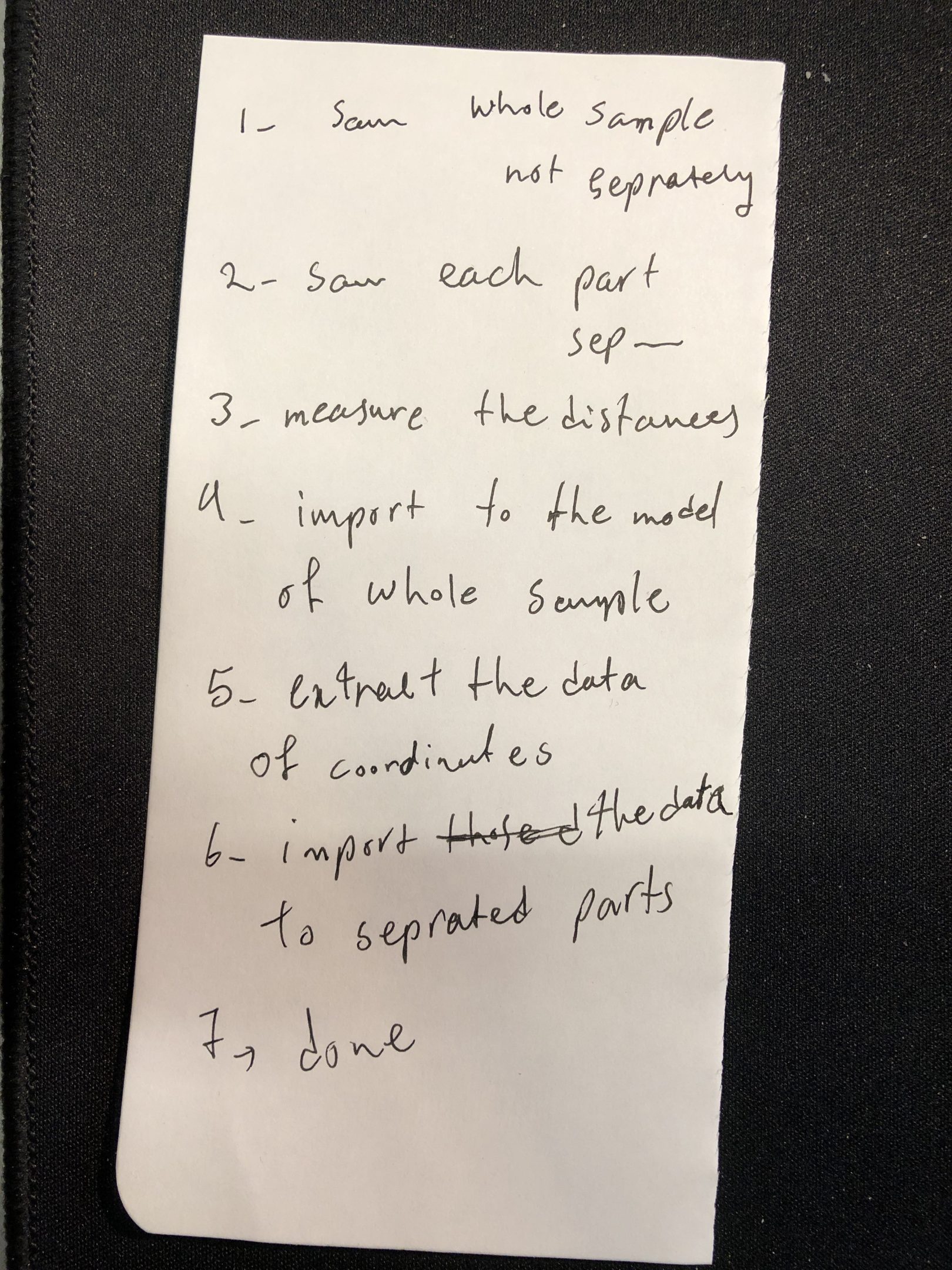
- scan whole sample together
- scan each part separately
- measure the distances between markers
- import the distances to the model of the sample together
- extract coordinate data
- import the data to separated parts
- done
The coordinate data is X,Y,Z positions. It can be tested with CloudCompare – Open Source project
In this example I used: Circular, single ring, 12-bit.
These particular markers can also be used with Agisoft photogrammetry software. The 2 circle and other markers might not be compatible.
70 markers template
30 markers template
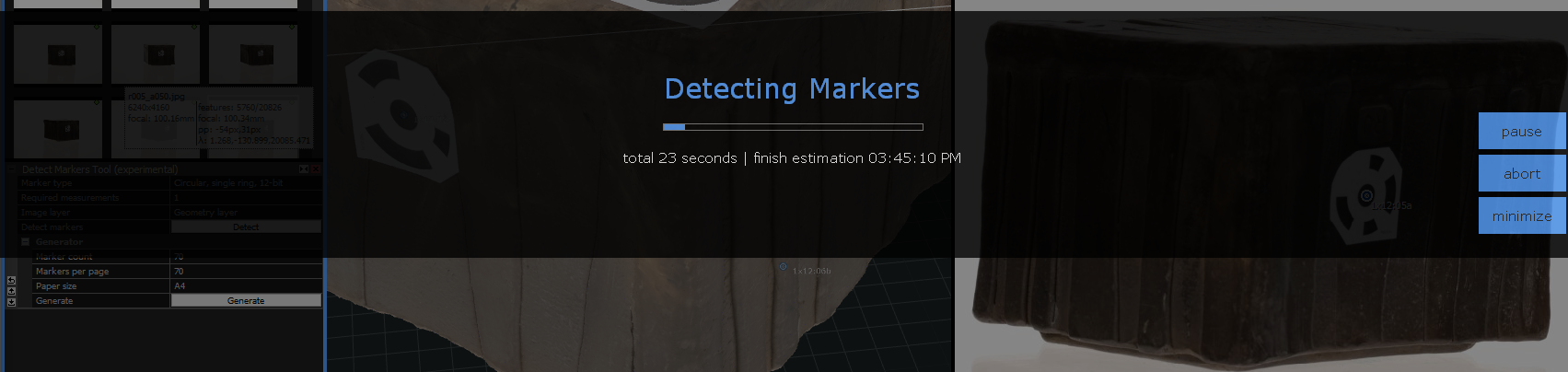
Import photos into RC. Then hit the DETECT button in the Detect Markers Tool (Experimental) menu. This step identifies the markers that have been placed on the object and also ALIGNS IMAGES.
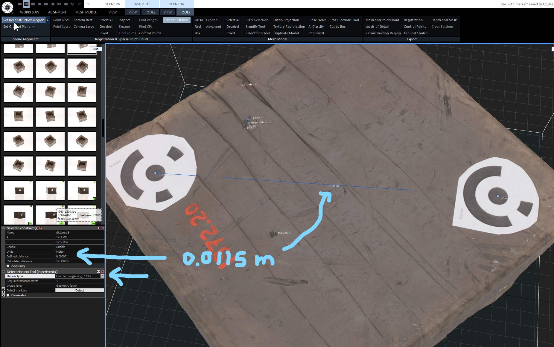
To define a distance goto TOOLS tab, DEFINE DISTANCE and then in the menu DEFINED DISTANCE enter a measured value (with calipers or a ruler). The markers have a white circle in the very middle to help with this.
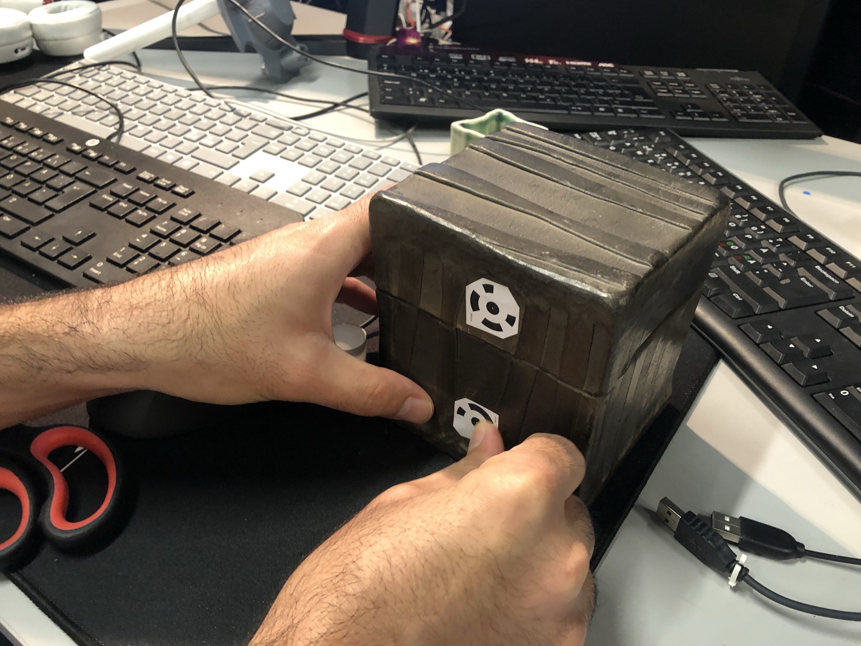
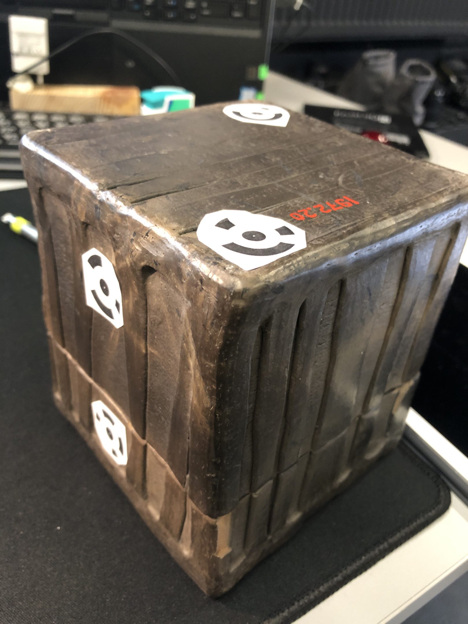
WHERE to place markers?
In a way the more the merrier but I don’t want to ruin the object that’s being scanned… It should be possible however, to take duplicate photosets with and without the markers and then use the texture from the non-marker set – but this needs to be looked into.
There should be 2 markers on a single side to get scale.
There should be 2 markers on a single side -but on the separate objects in order to align objects. E.g. The a box and lid. So have 2 markers on the same wall for the lid and for 2 for the box, and then 2 markers where one is on the box and the other on the lid, but on the same side.